Once upon a time, in a distant era long gone by, TI (Texas Instruments) were in the business of making and selling GSM MS chipsets, i.e., chip-level building blocks from which other companies (downstream in the supply chain) would then build GSM phones or sometimes more specialized modem products. To the best of our understanding, they got out of this business some time around 2009; toward the end they had chipsets that supported EDGE (EGPRS) for sure, and perhaps even UMTS/3G. (We know for sure that they did significant development on 3G; the part where we are less certain is whether or not those developments resulted in shipped products.) However, out of this long history of TI GSM MS chipset evolution, there is one particular chipset, one specific (and quite arbitrary) point on the evolutionary line, which I (Mother Mychaela) adopted as my own: the chipset named Calypso, after the nymph goddess in Homer's Odyssey. (During at least one period in their long history, TI's GSM MS chipset group used code names from Greek mythology.) Recreating the full environment that once existed around this Calypso chipset is one of the main goals of FreeCalypso GSM MS project.
When TI were in this GSM MS chipset business, they made and sold chips, not complete phones. However, in order to prove their chips as good and provide a more complete starting point for their customers (manufacturers of phone handsets and specialized GSM modem products), TI made not only chips, but also development (or reference) boards and reference firmware that ran on those boards. In FreeCalypso project we use original TI-made chips, but we seek to recreate the most interesting features of TI's original development boards in our own FC devboard designs, and we maintain our own reconstruction of TI's original firmware suite that once ran on their devboards.
Unlike newer GSM MS designs in which the entire MS is implemented in a single chip, TI Calypso chipset from early 2000s is comprised of multiple chips:
Calypso is a DBB chip: it contains an ARM7TDMI CPU core that runs high-level firmware, a TMS320C54x DSP core with a large mask ROM, and various specialized peripherals for its function as GSM MS. But it is almost entirely digital, containing no power conversion, analog or RF functions, hence the name DBB.
Calypso DBB requires a specialized companion ABB chip. The two supported ABB options are Nausica, the ABB chip that was originally developed for earlier DBBs prior to Calypso, and Iota, the ABB chip developed specifically for use with Calypso. Iota ABB provides power regulation (from battery power source to fixed voltages required by various components), on/off control, battery charging, ADCs and DACs for the baseband path (I and Q) and for voice calls (earpiece and microphone), SIM card multivolt interface and some miscellaneous functions. Its predecessor Nausica was supposedly similar, but we have no documentation for it.
TI's Syren ABB, successor to Iota, officially made for use with Calypso+ and found on TI's E-Sample board, is also compatible in theory with classic Calypso — but we are not aware of any actual board-level designs that combine Calypso DBB and Syren ABB. Furthermore, there is no complete support for Calypso+Syren combination in TCS211 reference firmware.
The coupling between the baseband chipset and the RF transceiver is much looser than that between DBB and ABB: some historical GSM phones and modems exhibit a design where TI Calypso+Iota baseband chipset drives a non-TI RF transceiver, usually Silabs Aero family. However, once TI started making their own RF chips for GSM MS, they naturally preferred those to their competitors. During the late Calypso era that serves as our golden reference, TI's official RF transceiver chip was Rita, forming the full chipset as Calypso+Iota+Rita. Rita's predecessor was Clara — but just as with Nausica, we lack any documentation for Clara RF.
All of these chips have been out of production for almost two decades at this point. However, I (Mother Mychaela) have a stash of these chips that should be sufficient for me to make some more boards for my own use and enjoyment, and to share with those very few people whose world view is close enough to mine to where they deserve one of these boutique FreeCalypso boards.
We are aware of the following historical evolutionary revisions of Calypso silicon, all of which are variants of classic Calypso rather than Calypso+:
There also exists a version of final Calypso C035 silicon with reduced internal RAM: 256 KiB instead of 512 KiB found in the full Calypso. This cost-reduced version is called Calypso Lite and has no other differences beyond reduced internal RAM capacity.
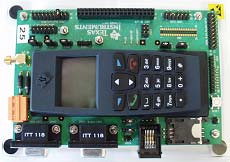
The first TI development board with Calypso DBB was C-Sample. We have never seen a C-Sample board in real life, but it is plausible that this photo, extracted from TI's Riviera presentation, may be of a C-Sample board. The resolution of this photo is far too low to make out any details, but it is consistent with our understanding of what hardware features existed on C-Sample.
What we do know about C-Sample, reconstructed from bits and pieces of knowledge found in some docs and firmware sources, is that the core chipset was Calypso DBB, Nausica ABB and Clara RF. Furthermore, the Calypso DBB version had to be C05 rev A or C05 rev B, but not C035: it appears that Nausica ABB is incompatible with DBB chips that require 1.5 V core voltage rather than 1.8 V. (By the time Calypso C035 came out, TI had moved on to D-Sample platform, see below.)
In terms of handset UI peripherals, C-Sample featured an 84x48 pixel black&white LCD, exactly the same as on certain classic Nokia phones — and given that Nokia and TI were best buddies during this time (a close symbiotic relationship), it is likely that Nokia simply gave TI those LCDs for use on development platforms. The set of keypad buttons on C-Sample was exactly what we see in the low-resolution photo linked above — hence our educated guess that this photo may be of a C-Sample board.
C-Sample development board was followed by D-Sample: the first board to feature Iota ABB. Nausica was replaced with Iota, RF is still Clara, and the range of Calypso silicon versions is newer:
In terms of its peripherals, D-Sample is a very interesting board, and we have a dedicated page for it.
Very shortly after D-Sample, TI produced another devboard family called Leonardo. What makes Leonardo more complicated is that it was not a single, one size fits all devboard design — instead there was a rather complex history of different Leonardo variants, sometimes with multiple variants intentionally maintained in parallel. We likewise have a dedicated page for Leonardo variants.
Most mobile phone chipsets, including our beloved Iota, Rita and
the associated RF PAs, are designed to be powered by a battery,
either a single Li-ion cell or 3 NiMH (or NiCd) cells in series.
All TI devboards in this family, including C-Sample, D-Sample and Leonardo,
were designed to accept raw
battery-emulating power, or perhaps
an actual battery, as opposed to accepting some higher voltage input
(such as 5V) and then generating battery-emulating power with an on-board
buck regulator.
As a further detail, the power input connector on C-Sample and D-Sample boards, as well as all known later variants of Leonardo, is Weidmuller 1510460000 — it is the bright orange connector visible in all historical TI photos of these boards. The mating connector that terminates the power feeding cable is Weidmuller 1716330000.
On our own FreeCalypso devboards, we have copied this aspect of TI's
original design: our boards also take in raw
battery-emulating power
(usually 3.6 V nominal) and even feature the same exotic
power input connector.
The intent was and is to fully recreate the authentic experience
of an engineer working with TI's original devboards back in the early 2000s.
TI's GSM MS chipset solution consisted of not only chips and development or reference boards, but also reference firmware that ran on those boards. During the period of TI history which I (Mother Mychaela) adopted as my golden reference, their GSM MS reference firmware suite was called TCS2.1.1, or TCS211 for short. The two official hardware platforms for TCS211 were D-Sample and Leonardo — although as we only understood much later, only certain versions of Leonardo could be used to exercise the full functionality of TCS211.
Unfortunately the complete source for TCS211 appears to have been lost. Instead the only surviving version (known to us) of this once-great and versatile firmware suite is a special version that was prepared in 2007 by TI-Taiwan support group for a small obscure company that operated on that island in those days, a version that was delivered in what we call semi-src form: about half source, half linkable binary objects. This delivery was built for a target that was a derivative of Leonardo with permuted RFFE control signals; since the binary object portion includes all of L1 and RF control, we thus got RF driver code only for Rita and not for Clara.
As described on our software page,
we have now deblobbed TCS211 L1, i.e., painstakingly reconstructed
new C source modules that compile into the same code as the original blobs.
However, since we never got TCS211 tpudrv10 (Clara RF) code
in any form, neither source nor object, we can only run our firmware
on Leonardo derivatives, and not on D-Sample.