Unlike D-Sample which was a single,
well-defined platform, TI produced a whole slew of different boards
that were some variation of Leonardo.
Making sense of that mess as an outsider who wasn't there during the day,
working with only fragmented bits of information
(whatever tidbits we were able to find), took quite a long time,
and there were significant stretches in FreeCalypso project history
when I (Mother Mychaela) operated under incorrect assumptions
regarding what I erroneously viewed as the
Leonardo platform.
However, as I write this web page in 2026, I feel more confident
that I finally reconstructed the most likely true history of
these Leonardo boards — so here it comes.
In surviving bits of TI documentation, sometimes the name Leonardo
is followed by a plus sign, other times it isn't.
It appears that TI's devboard group in Denmark (Aalborg) produced both
plain
Leonardo and Leonardo+ boards in parallel throughout
most of this board family's history, producing new versions of both
boards each time they made an evolutionary revision.
Leonardo+ was a fully quadband GSM MS based on
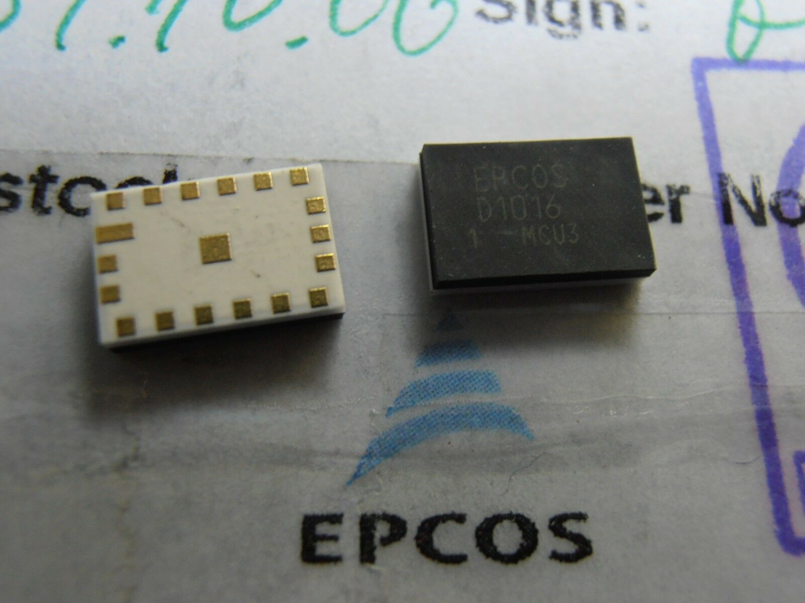
Epcos D1016
quadband RFFE, whereas plain
Leonardo was hobbled to support
only two GSM frequency bands for a single region, either EGSM900 and DCS1800
or GSM850 and PCS1900.
Furthermore, the 2-band Leonardo and the 4-band Leonardo+ were two
different PCB designs at each evolutionary revision, not just different
population options on the same PCB.
To a FOSS engineer like Mother Mychaela, this practice of maintaining
both a full-featured GSM MS development board and a hobbled version
in parallel appears absolutely bizarre and irrational.
In order to understand why they did it the way they did,
we have to remember that TI's engineers who designed and built these boards
were not free artisans like FreeCalypso or Osmocom developers,
but rather employees of a marketroid-driven corporation where decisions
are made under irrational, anti-human and anti-enlightenment forces
of the market.
As explained here,
early in the 2000s decade the cellular phone industry came up with its
low-end
vs high-end
distinction;
per this doctrine, it was considered improper
to equip a low-end
Calypso phone with a quadband RFFE.
We don't know of any mass-produced, widely available Calypso phones
that were made quadband: high-end
models in the days when TI Calypso
chipset was current were made triband, but most Calypso phones were assigned
to low-end
category and made with only 2-band, single-region RFFEs.
It appears that Leonardo platform was the reference design which
TI presented to their customers (phone manufacturers), and apparently
it was important to present them with not only the universal devboard
that supports everything, but also a version that matches their low-end
orientation.
It appears that the earliest generation of Leonardo boards
(presumably both plain
and plus
)
were made as true handset prototypes, such that one could take
one of those early Leonardo boards, stick it into a plastic case
and get an actual, usable basic GSM phone handset.
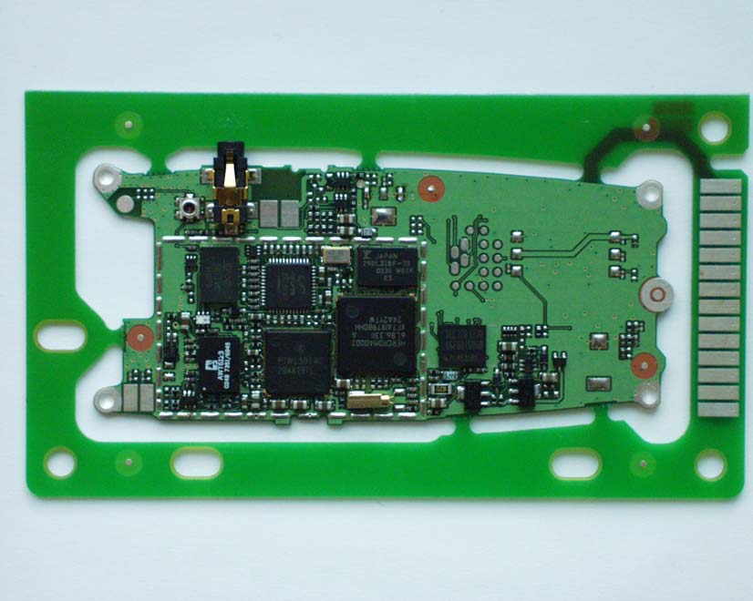
We make this claim based on
this photo,
extracted from
this marketing presentation.
In this photo we see a board whose physical form factor is exactly
as I just described, and the marketing presentation (on slide 10)
identifies it as Leonardo.
The board depicted here is the quadband plus
variant:
the quadband FEM (Epcos D1016) is clearly visible, and the board
is also described as quadband.
It is noteworthy, however, that this board is not fully populated:
notably missing are the battery connector and the SIM socket.
However, the exterior frame from which the inner board is meant to break out
is not solely mechanical: it also features contact pads and traces that
connect these production test pads to circuits inside the main inner portion.
Comparing the visual appearance of these production test pads against
the available schematics for later Leonardo versions (see below),
we can figure out which signals are brought out — and sure enough,
the set of signals on the production test connector includes battery power,
UART, SIM interface, PWON and RESET controls, i.e., everything needed
for bring-up.
If we look very closely at the markings on the Calypso DBB chip on the board in this photo, one can make out that it says F741979BGHH — the exact same marking as appears on the Calypso DBB chip on our D-Sample board from 2002. This chip version is Calypso C05 rev B, supported by TI's firmware as CHIPSET 8. This photo serves as evidence that the earliest Leonardo boards predate Calypso C035, and this particular board was indeed one of those earliest.
In this photo we see only the side of the board that would be considered the bottom in a standard phone assembly, the side that features the battery connector, the SIM socket and most chipset components. The side that is normally considered the top, featuring the LCD and the phone keypad, is not visible in this photo — but we do have schematics for some later Leonardo versions and even a component placement drawing for one of them. Based on this documentation, I can say confidently that this early Leonardo design features the same UI elements as TI C-Sample: the same 84x48 pixel black&white LCD (serial interface) and the same set of included keypad buttons, although in a slightly different wiring arrangement.
Whatever plans TI may have had when they produced these early Leonardo boards, it seems that C-Sample-like phone UI support for Leonardo never appeared in TI's TCS211 firmware or its direct lineage predecessors. I say so based on these two observations:
TI's firmware code base makes heavy use of C preprocessor conditionals
to select different configurations.
Aspects which relate to core chipset distinctions are conditionalized
on CHIPSET, DSP, ANLG_FAM and RF_FAM preprocessor symbols,
but code that deals with phone handset peripherals (LCD, keypad, backlights,
battery charging, GPIO lines) is conditionalized on BOARD symbol.
However, no distinct BOARD number was ever assigned to Leonardo —
instead it shares BOARD number 41 with D-Sample.
It would be possible to distinguish between D-Sample and Leonardo
by checking RF_FAM preprocessor symbol in addition to BOARD —
but with one possible exception (GPIO 2 direction setting in
init.c module which we only got as init.obj),
we just don't see any code written so.
Instead all firmware code that deals with UI peripherals simply assumes
that BOARD==41 means D-Sample, and compiles into the D-Sample
version.
The keypad driver in TCS211 (which we got in full source) has keypad wiring tables going back to B-Sample. B-Sample, C-Sample and Leonardo all share the same 18-button keypad design, but the exact wiring is different on each of these 3 boards. The driver has tables for B-Sample and C-Sample, but not for Leonardo.
There exist 3 Leonardo board versions for which we got schematics: Leonardo+ rev 4, Leonardo+ rev 5 and Leonardo 2-band rev 5. All 3 schematics identify the Calypso DBB chip as PD751992GHH (Calypso C035 with DSP ROM 3606, i.e., the final Calypso), thereby confirming that this dust-settled Calypso silicon version was already in existence as of 2003-October, the date of these schematics. Furthermore, board wiring in these schematics does not allow Calypso C05, only C035: Iota VLRTC is tied directly to GND, with no option of pull-up.
Unlike the early Leonardo version (with Calypso C05 rev B) covered in the previous section, these Leonardo versions are more proper devboards, intended for use on a lab bench:
Out of the 3 schematic PDFs we got, the one for Leonardo+ rev 4 also includes a component placement drawing. (TI's devboard group used OrCAD for schematics and PADS for PCB layout, hence this PDF must be a composition made from separate OrCAD and PADS exports.) By comparing this Leonardo+ rev 4 (or perhaps a slightly earlier revision, based on dates in the drawing titleblock) component placement drawing against the photo of the early Leonardo+ version that was meant to go into a plastic case as a true handset prototype, we can clearly see the evolution from the latter (the handset prototype) to the former (the board for use on a lab bench). Furthermore, the exact set of included peripherals on these Leonardo versions (visible in the schematics for all 3 versions) and their placement on the board (visible in the one version for which we got the component placement drawing) only makes sense when we consider the predecessor from which these boards evolved — it would make no sense for a freshly designed devboard without this prehistory.
Leonardo boards of this generation still feature a connector for the small, serially interfaced LCD which we presume was inherited from C-Sample and earlier, and a keypad of 18 buttons, now located on the side of the board that becomes the bottom in typical devboard usage. I am going to venture a strong guess that these Leonardo UI provisions were probably never used, and the respective components were most likely not even populated. The argument presented in the previous section regarding the lack of firmware support applies here equally, and these UI elements become physically unusable in the new form factor adopted in this Leonardo generation. Therefore, I venture an educated guess that these Leonardo boards were most likely exercised only with ACI firmware builds, controlled via AT commands.
In Leonardo+ (quadband GSM MS) lineage, an important change happens
going from rev 4 to rev 5: arrangement of flash and RAM.
On Leonardo+ rev 4 and apparently on all previous versions going back
to the one with Calypso C05 rev B in the form factor intended for
a plastic case,
flash and board-level SRAM (what we call XRAM in FreeCalypso)
are in two separate chips, with only the flash chip located neatly
in the shieldcan section.
Flash capacity is 4 MiB and XRAM capacity is 512 KiB.
On Leonardo+ rev 5 this situation changes: a combined flash+RAM MCP
is used for the first time (I suspect we are seeing the point in time
at which these MCPs became available), and the PCB footprint and wiring
support MCPs with up to 16 MiB of flash and up to 8 MiB of XRAM.
The flash chip table in devices.txt that came with
TI's FLUID version 2.27 indicates that the MCP actually populated
on these boards was a same-ID predecessor of Spansion S71PL129J:
the flash component is two chip select banks of 8 MiB each.
This detail is important because it matters for TI's official TCS211
firmware.
Looking at the documentation and XML config files that came with our
2007 version of TCS211, we can see that only a very restricted
configuration was supported for Leonardo version 4
with 4 MiB
flash, while most other Leonardo configs require 8 MiB AMD flash
— they are referring to just the first bank which is indeed 8 MiB.
It is also worthy of note that this flash change from rev 4 to rev 5
happened only on 4-band Leonardo+ and not on 2-band
plain
Leonardo: rev 5 of the latter still features the original
arrangement with 4 MiB of flash and 512 KiB of XRAM.
The most likely explanation is the same
marketing think that motivated the creation of
and ongoing support for the hobbled 2-band version in the first place:
this 2-band Leonardo version was intended for low-end market segment
,
those low-end
phones don't need extended features, and hence don't
need the larger flash and RAM to support them.
For a long time I could not understand this conundrum:
Because Leonardo does not have its own BOARD number but shares BOARD number 41 with D-Sample, all UI code in TCS211 firmware compiles for D-Sample (expects the 176x220 pixel color LCD with a parallel interface in D-Sample wiring, as well as D-Sample keypad wiring) even when the selected build target is Leonardo. But how can it work if our known Leonardo schematics depict very different UI hardware that is more like C-Sample?
The set of officially supported configs listed in TCS211 documentation includes high-end configs with phone handset UI and various extra features (WAP, MMS etc) for both Leonardo and D-Sample targets. But how can it work when the necessary D-Sample UI hardware does not exist on Leonardo?
It seems almost as if TI later produced a new version of Leonardo
that has a core from previously examined Leonardo+ rev 5, but also adopts
UI peripherals from D-Sample.
Then one day I was taking a closer look at the flash chip table in
devices.txt that came with TI's FLUID version 2.27,
and saw this stanza:
/* Flash used on Esample Rev4, Leonardo+ REV5 and Leonard Sample REV1 */
/* Multi-id device: 0x227E, 0x2221, 0x2200. Converted to 0x2100 */
device Am29DL640F 0x01 0x2100 amd map_8x8_126x64_8x8 /* 8 + 24 + 24 + 8 */
The device ID code matches Spansion S71PL129J; the described geometry
also matches closely enough for the kind of flashing operations FLUID
was used for.
But what about that comment — what is Leonard Sample REV1
,
following after Leonardo+ rev 5?
Could it be the answer to the mystery questions I posed at the beginning
of this section, a board that effectively combines the best of Leonardo
and D-Sample?
The naming certainly suggests so!
As a further clue, documentation that came with our 2007 version
of TCS211 describes the Leonardo target (supported along with D-Sample)
as Leonardo + board Rev 2
.
OTOH, FLUID version 2.27 and its devices.txt file
date from 2004, and refer to Leonard Sample REV1
.
What if TCS211-2007 docs really mean Leonardo Sample when they say
Leonardo+
, and what if this Leonardo Sample platform evolved
from rev 1 to rev 2 between 2004 and 2007?
This hypothesis is the only explanation that makes sense...
Needless to say, I have never seen this theorized Leonardo Sample board,
hence I can only guess what it was like.
If I were the engineer tasked with designing and building this article
within the environment of TI of the first half of 2000s decade,
I would have taken the design of Leonardo+ rev 5 and repackaged it
into the form factor of their D-Sample and E-Sample boards, so it
would fit into the same lunch box
.
Keep Leonardo+ core intact, but remove all those weird peripherals
which TCS211 fw never supported, and allow the same handset that is
used with D-Sample (unchanged for E-Sample or not, uncertain) to work
with this Leonardo Sample board.
Perhaps TI did exactly what I just outlined, or perhaps it was
something different — we'll probably never know.
In any case, the proper solution for FreeCalypso is to build our long desired Venus board, that will be essentially our own equivalent of Leonardo Sample.